THD analysis
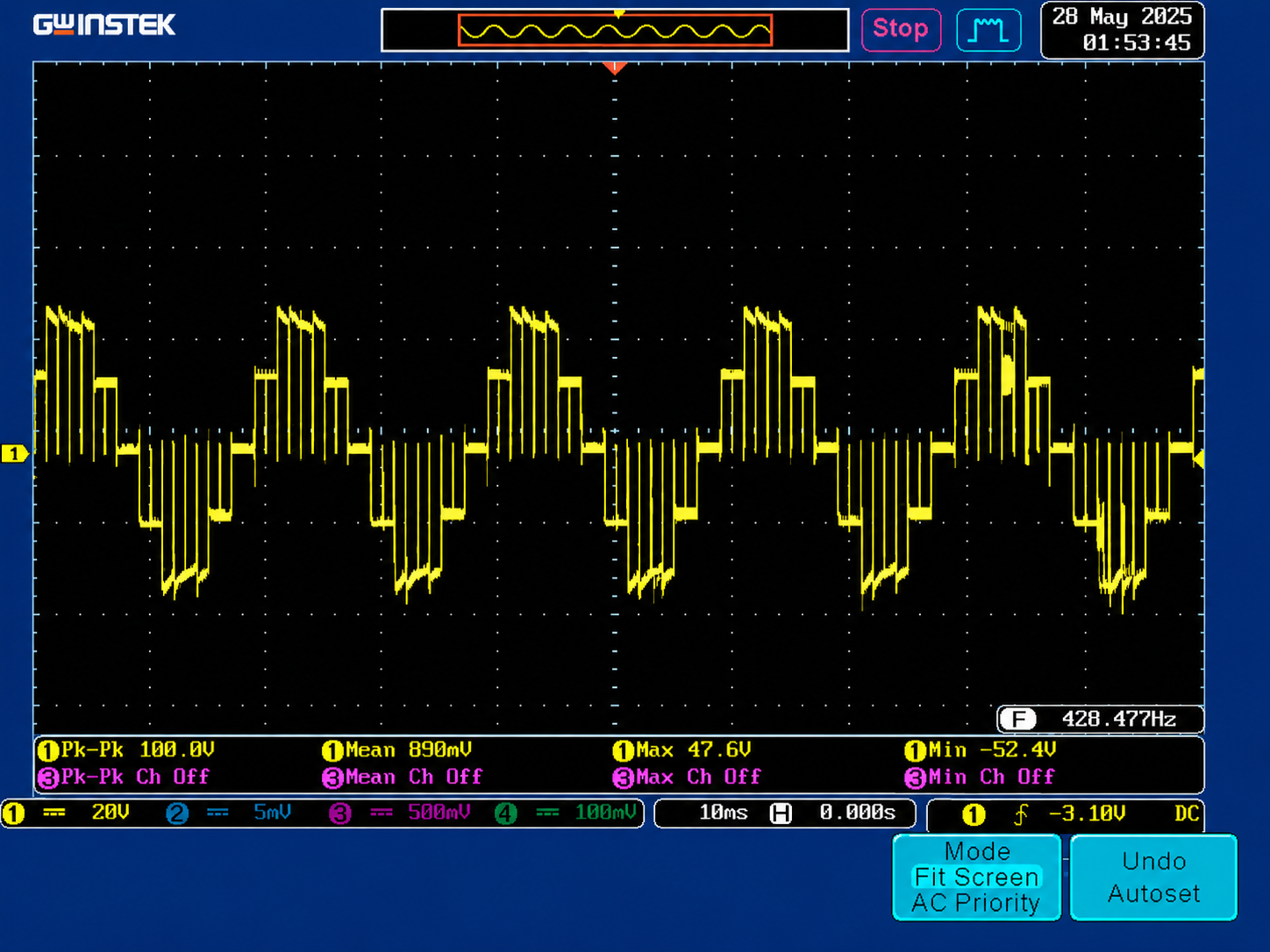
Pre-hardware (simulation)
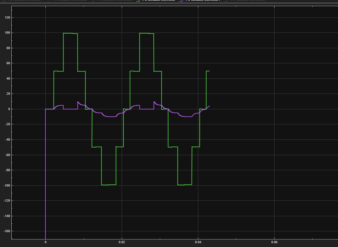
The Simulink LS-PWM model predicted THD = 4.9 % at the headline operating point (5 kHz switching, 50 Hz fundamental, modulation index 0.95, resistive load ≈ 400 W). This figure is the one quoted in the ELE 401 interim report and the ELE 402 interim report v4.
Why 4.9 % is the design target:
- IEEE 519-2022 limits voltage THD to ≤ 8 % for systems below 1 kV at the Point of Common Coupling.
- 4.9 % gives a comfortable margin (≈ 40 %) below the standard limit.
- LS-PWM trades ≈ 0.5 % more THD than PS-PWM (4.4 % vs 4.9 % in textbook comparisons) for simpler implementation — the team accepted that trade for the simulation phase, then switched to PSC in the firmware once the IPD-induced bridge-loss asymmetry showed up.
Bench (post-bring-up)
Awaiting capture
The bench-validated THD number needs the team's final FFT capture from a sustained PSC run. Once available, it will appear here side-by-side with the 4.9 % simulation figure. Tracked at _AGENT_TRACKER.md — artifact #8.
LC filter implications
The team prototyped two LC filter values during the design phase:
| Variant | L | C | fc |
|---|---|---|---|
| Initial design | 15 mH | 22 µF | 325 Hz |
| Revised for RL load | 15 mH | 30 µF | 237 Hz |
These were both characterised in the chb-5level-rl-nospike.slx model. The team also kept notes (in the LC design discussion) on the cutoff trade-off — lower fc attenuates the switching-frequency harmonics harder but also softens the dynamic response.
The bench filter is not yet built — the demonstration ran the inverter into a resistive load with no output filter, so the 5-level cascade is visible directly on the scope. The roadmap item LC filter tracks adding the filter to push pre-load THD further down.