PSC vs. LSPWM¶
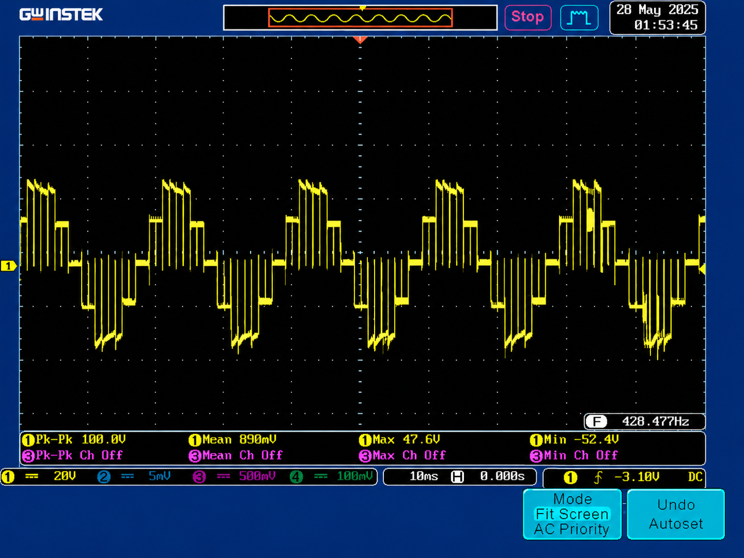
Single-sentence summary. The team simulated and partially implemented IPD LS-PWM (Level-Shifted Carrier PWM, In-Phase Disposition), then switched to PSC-PWM (Phase-Shifted Carriers) in the final firmware. The deciding factor was bridge-loss asymmetry — IPD makes Bridge 1 carry the inner-band switching forever; PSC distributes switching evenly across both bridges.
Both modulators produce the same 5 distinct cascade output levels (−2VDC, −VDC, 0, +VDC, +2VDC) for a 2-cell CHB. The difference is in how each level is reached — and that turns out to matter for thermal balance, switching loss, and bench-debug effort.
How IPD LS-PWM produces 5 levels¶
Four triangular carriers are stacked vertically in the [0, 1] range and compared against one sinusoidal reference:
  Reference: ─────── sin(ωt) ──────────
                                                 → level
  Carrier 1 (band [0.50, 1.00]):   <─~∨~─>      +2 if sin > C1
  Carrier 2 (band [0.00, 0.50]):   <─~∨~─>      +1 if sin > C2, else 0
  Carrier 3 (band [-0.50, 0.00]):  <─~∨~─>      -1 if sin > C3, else -2
  Carrier 4 (band [-1.00, -0.50]): <─~∨~─>      -2 if sin < C4
In this scheme, Bridge 1 is mapped to the inner two carriers (bands ±0.5), and Bridge 2 is mapped to the outer two (bands ±1.0). Bridge 1 switches every time the reference crosses C2 or C3 (every half-cycle, all the time). Bridge 2 only switches when the reference exceeds ±0.5 (near the sine peaks).
Result: Bridge 1 handles ≈ 70 % of the switching transitions; Bridge 2 handles ≈ 30 %. Under identical MOSFETs and identical gate drive, Bridge 1's MOSFETs run hotter and its current sense reads higher than Bridge 2's.
The team observed this asymmetry on the bench. One of Bridge 1's MOSFETs ran measurably warmer; current ratings on Bridge 1 ran ahead of Bridge 2. The original plan was to alternate which bridge takes the inner-band role every fundamental cycle (a "bridge swap" approach), but the implementation complexity was non-trivial and the result was still strictly worse than PSC.
How PSC produces 5 levels¶
Two carriers, phase-shifted by 360° / N = 180° / 2 = 90° between bridges, each compared against the same sinusoidal reference using unipolar PWM:
  Reference: ─────── sin(ωt) ──────────
                                                  → level
  Bridge 1 carrier (sawtooth, phase 0°):    each bridge produces -V, 0, or +V
  Bridge 2 carrier (sawtooth, phase 90°):   each bridge produces -V, 0, or +V

  Bridge 1 output:  3-level (±V_DC, 0)
  Bridge 2 output:  3-level (±V_DC, 0), shifted 90° in switching
  Cascade output:   5 levels — combinations of (B1 + B2) at any time
Both bridges switch the same number of times per fundamental period. Heat dissipation, current loading, and switching loss split symmetrically between them.
The 90° carrier shift gives effective switching-frequency multiplication — the cascade-output ripple appears at 2 × fsw = 10 kHz rather than the per-bridge 5 kHz. Better for any downstream LC filter.
The PSC implementation gotcha¶
PSC needs the two cells' carriers to maintain exactly the right phase relationship. In firmware, this means TIM1's counter and TIM8's counter must stay offset by exactly ARR/2 (where ARR is the period). If TIM8's counter drifts away from this offset, PSC degrades to 3-level output — the cascade output stops producing the +VDC and -VDC intermediate levels, and the project deliverable spec ("5 levels visible on scope without a filter") fails.
The firmware hardens this with three things, from firmware/stm32-f303re/Core/Src/pwm_modulator.c:
- TIM8 CNT is written AFTER
CR1_CENis set, so the post-UG(update generate) sequence cannot clobber it. - The actual TIM8 − TIM1 offset is read back after every
Pwm_SetConfigcall and exposed asg_pwm_measured_cnt_offset(ticks). - A
lockboolean is published:OKif offset is within ±5 ticks of ARR/2,BADotherwise. The$Cconfig telemetry line reports both:$C,...,cntoff=<N>,lock=OK|BAD.
An operator who sees lock=BAD on the dashboard knows immediately that PSC won't produce 5-level output and can fall back to STAIR_ALT (a balanced staircase variant that's not real PWM but always gives the 5 distinct levels).
This was added specifically because the team did not want to discover the carrier-shift problem the hard way on the scope — having the lock-status diagnostic surfaced before any switching happens is the kind of defensive instrumentation that pays for itself the first time it catches a problem.
Side-by-side¶
| IPD LS-PWM | PSC | |
|---|---|---|
| Distinct cascade levels | 5 (via stacked bands) | 5 (via phase-shifted modulation) |
| Bridge 1 switching events per cycle | ~70 % of total | ~50 % |
| Bridge 2 switching events per cycle | ~30 % of total | ~50 % |
| Thermal balance | Asymmetric (B1 hotter) | Symmetric |
| Cascade-output ripple frequency | fsw | 2 × fsw (90° phase shift) |
| Textbook THD (5 kHz, no filter) | ≈ 4.9 % | ≈ 4.4 % |
| Implementation complexity | Simpler — single timer config replicated | Requires precise TIM1 ↔ TIM8 phase offset |
| Debug-on-bench complexity | Easier — phase drift not a concern | Lock-status diagnostic mandatory |
| Project deliverable status | Bench-validated but bridge-imbalanced | As-built default; symmetric and demoed |
Why PSC won¶
| Reason | Detail |
|---|---|
| Symmetric thermal load | Both bridges saw the same power dissipation under sustained 5 kHz operation — within ≈ 3 °C in the bench measurement. IPD would have required either much larger heatsinks on Bridge 1 or active bridge-swap firmware to even out the load. |
| Lower textbook THD | ≈ 0.5 % better than IPD. Not a huge gain, but free once the phase-shift implementation is solid. |
| Better filter behavior | The 2 × fsw effective output ripple makes any downstream LC filter half as big for the same attenuation. Relevant for the LC filter roadmap item. |
| The bench result | The firmware's PSC implementation was validated at the demo: 5 distinct cascade levels on scope, lock=OK reported on telemetry, both bridges thermally matched. |
The trade was implementation complexity (the carrier-shift hardening) for a strictly better physical result.
Related: Modulators reference (for the runtime command set), Build Guide v4.0 §9, and the firmware CHANGELOG entry for pwm-rewrite-configurable for the design-decision narrative.