Iteration 2 — revised gate-drive routing, bootstrap lessons
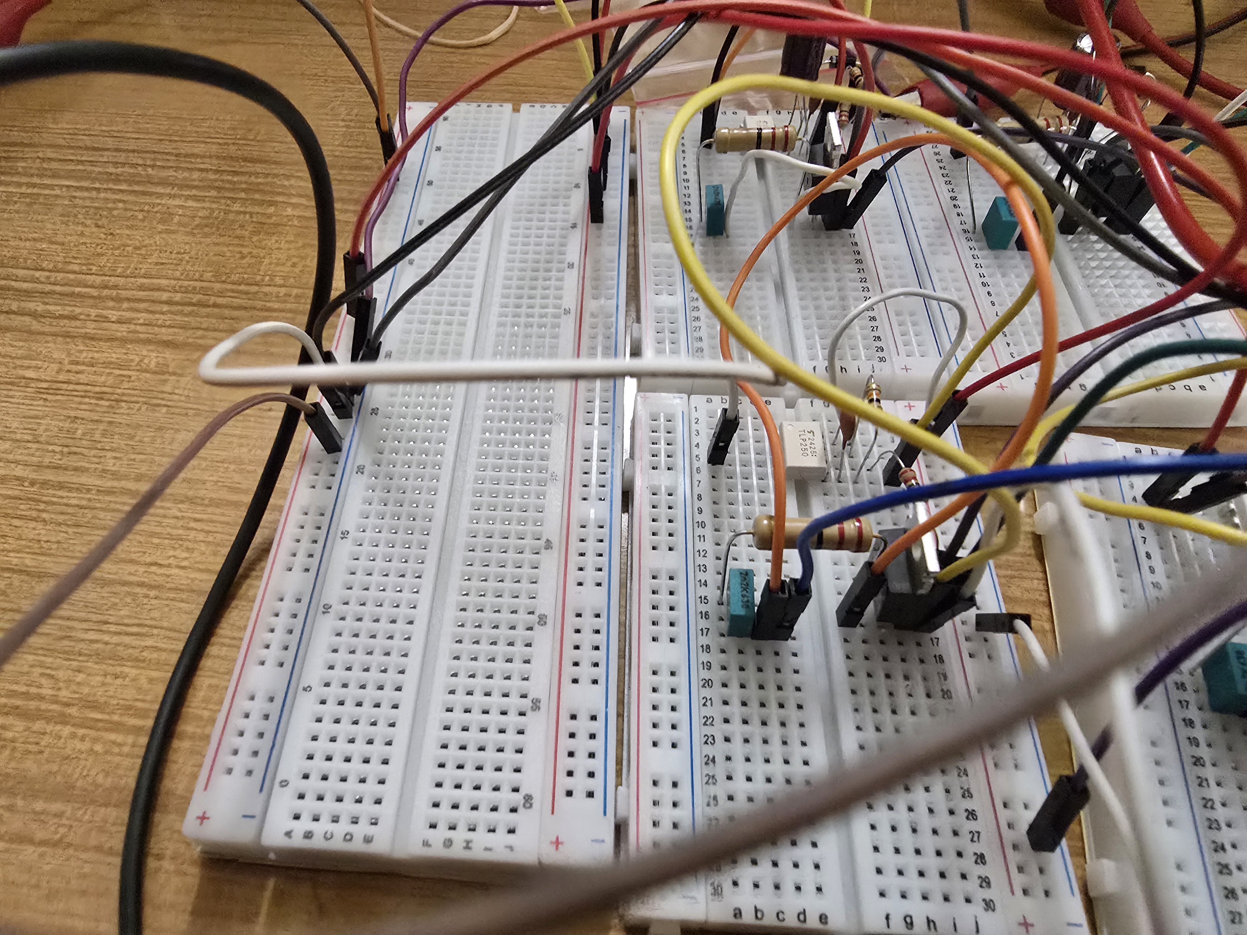
Status: superseded. KiCad files for iteration 2 are not preserved in the repo.
What was attempted
Iteration 2 kept the iteration-1 architecture (single dual-bridge PCB, IRFZ44N, IPD LS-PWM, 3-MISO sensing) and reworked the gate-drive routing in response to bring-up issues with iteration 1.
The main changes:
- Gate-loop trace lengths shortened — the iteration-1 layout had the TLP250 outputs running for several centimetres before reaching the MOSFET gates, picking up enough loop inductance to cause noticeable ringing.
- Gate resistor value tweaked — finer trade between switching speed (lower R) and shoot-through margin (higher R).
- Bootstrap diode and cap repositioned closer to the gate driver and the MOSFET source, reducing the bootstrap-loop length.
- Better decoupling on the TLP250 VCC pin — adding a 100 nF ceramic at every TLP250 instead of relying on bulk-only decoupling.
What failed
The headline failure was a bootstrap timing issue that didn't show up in the iteration-1 testing — once the gate-loop was tighter and the switching transitions faster, the bootstrap cap charge-time budget became visible:
| Failure | What happened |
|---|---|
| Bootstrap cap sagging at high duty | Running the inverter at modulation indices > 0.9, the bootstrap cap voltage drooped over consecutive cycles. HS gate voltage went below the IRFZ44N's Vth; the HS leg failed to fully turn on; output became distorted. |
| Floating-bridge bootstrap problem foreshadowed | The team noticed that Bridge 2's bootstrap path was structurally different from Bridge 1's — Bridge 2 sits at a floating reference, and the bootstrap diode had no real return to a stable ground. This was the early-warning that bootstrap drive cannot work for cascaded floating bridges. |
The bench symptoms looked similar to a noise problem at first. Diagnosing them as bootstrap-timing took a session and a careful look at the LS-on window vs. the bootstrap cap droop.
What was learned
- Bootstrap is a duty constraint, not just a parts choice. The 95 % HIGH-duty clamp that landed in the firmware in iteration 4 has its origin here — iteration 2 was the first time the team saw what happens when the LS-on window is too short to refresh the bootstrap.
- The 6 ms precharge sequence is necessary. Before iteration 2, the firmware just enabled MOE and ran. After iteration 2, MOE-enable → 6 ms of forced-LS-on → then PWM. This is the PRECHARGE state in the FSM today.
- CHB needs isolated gate drive — not bootstrap. The Bridge 2 floating-reference problem became the deciding factor. The iteration-3 plan included committing to B0515S isolated DC-DC per bridge + TLP250 (already in place), removing bootstrap entirely from the picture.
What changed for iteration 3
- The bootstrap fixes from iteration 2 were carried forward, but the team committed to isolated 15 V per bridge as the long-term solution.
- The schematic added the B0515S DC-DC and the per-bridge isolated 15 V rail to feed the TLP250s.
- Schematic-level decomposition continued:
5v-15v_sch.kicad_schwas introduced for the B0515S subcircuit.
What did not change in iteration 2: - MOSFET part (still IRFZ44N — the VDSS headroom issue from iteration 1 wasn't addressed yet). - Modulator (still IPD LS-PWM — the thermal-imbalance was tolerated for one more round).
Related: Bootstrap fundamentals, CHB isolation.