Populated photos
Photos from the bench bring-up and graduation demo day for the as-built single-bridge v4 modules.
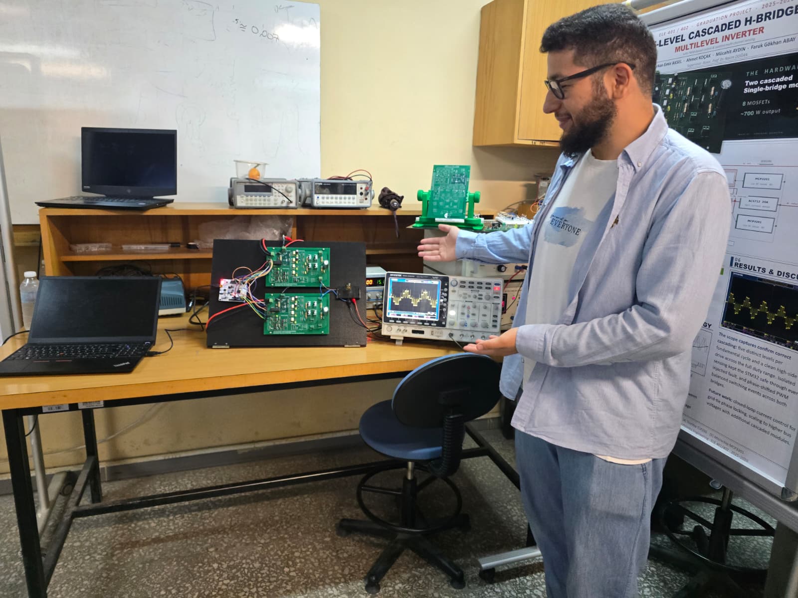
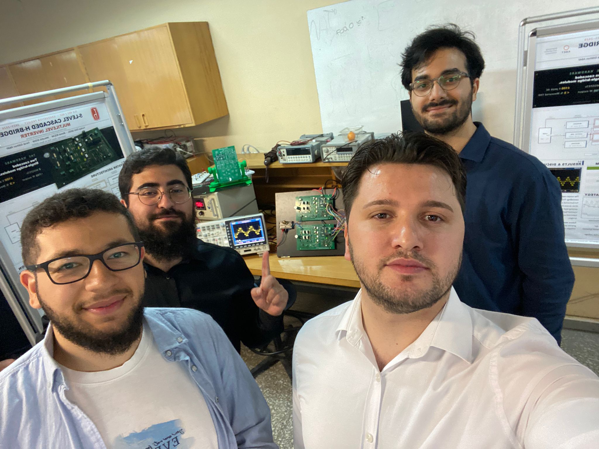
Demo day — the hero shots
The team's demo of the running 5-level cascaded inverter.
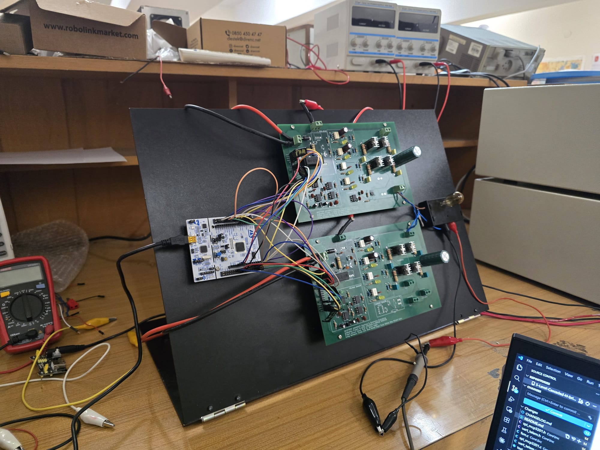
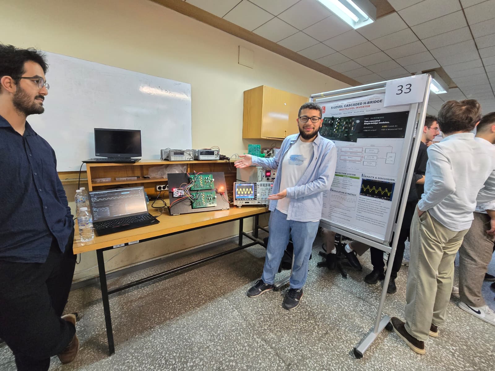
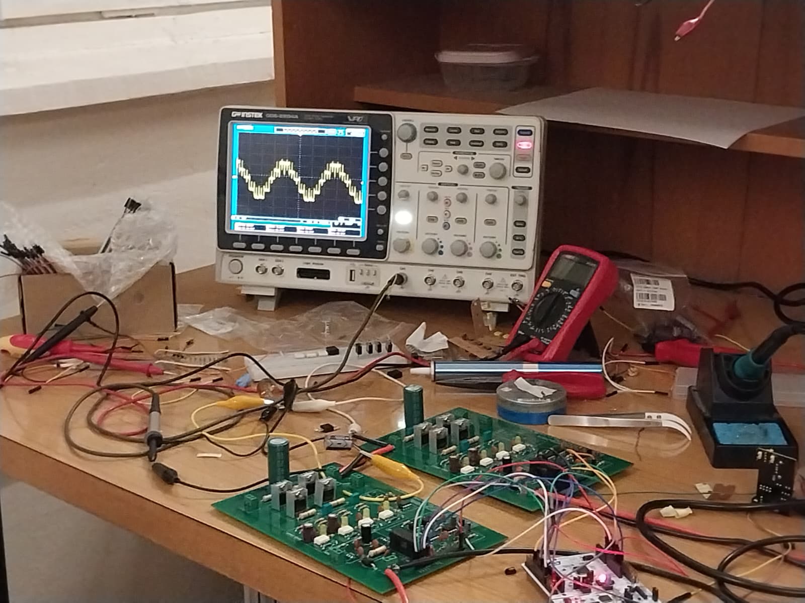
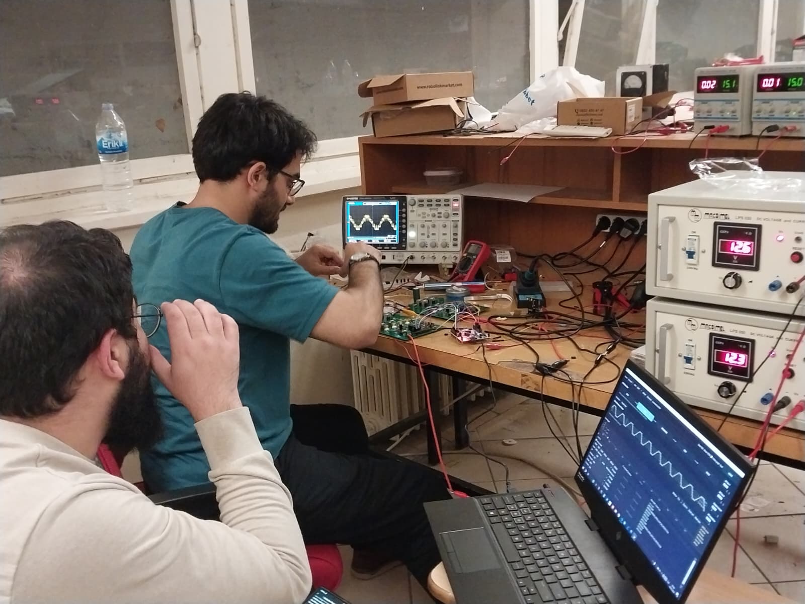
Oscilloscope captures
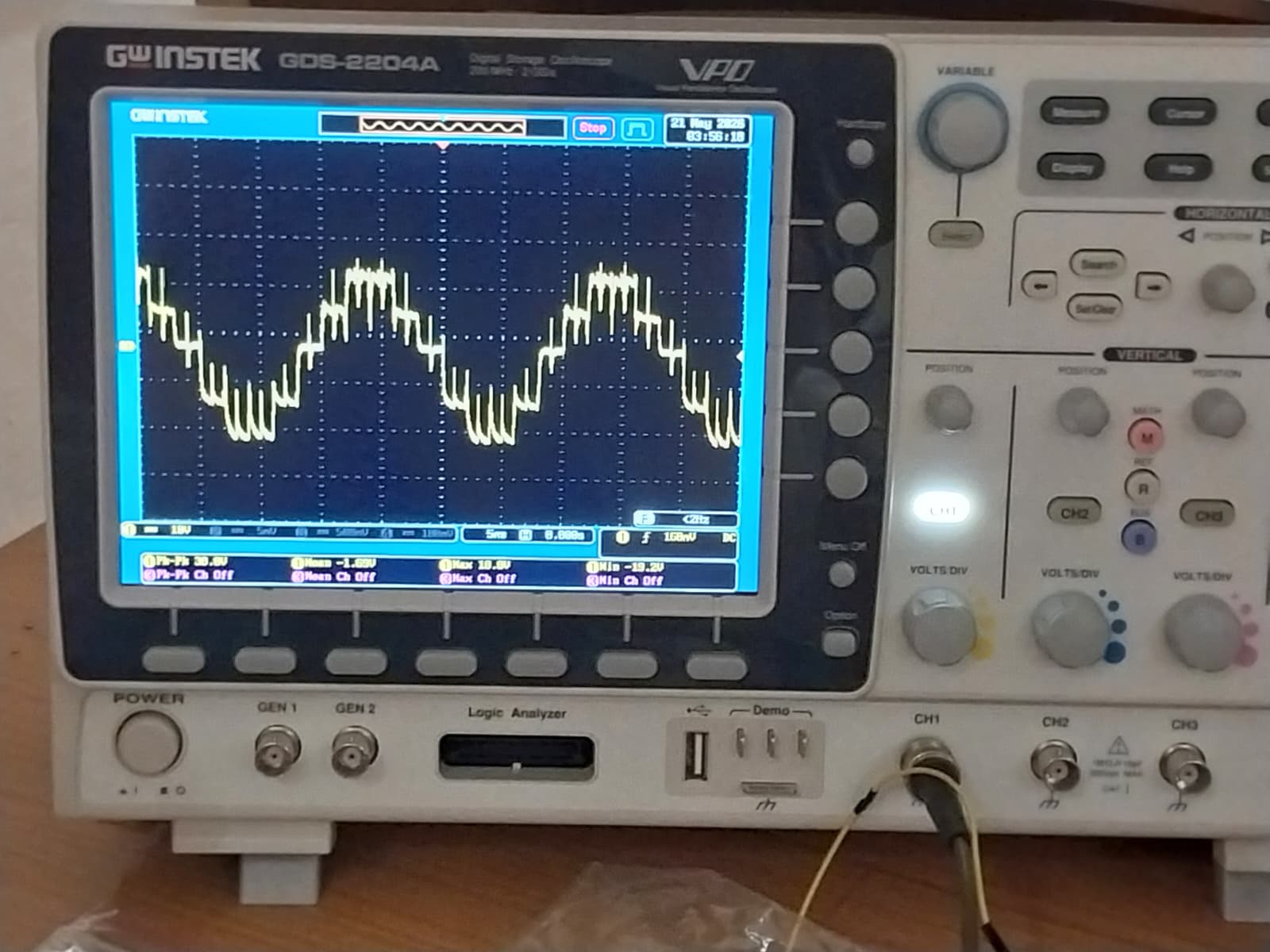
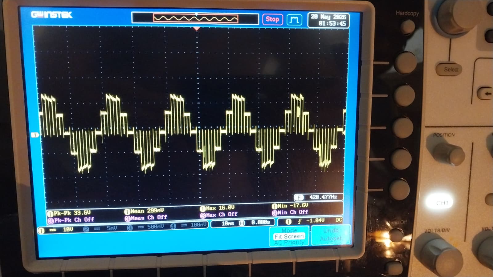
Headline — 100 V output, 5 distinct cascade levels
The project deliverable, captured on the scope at the demo:
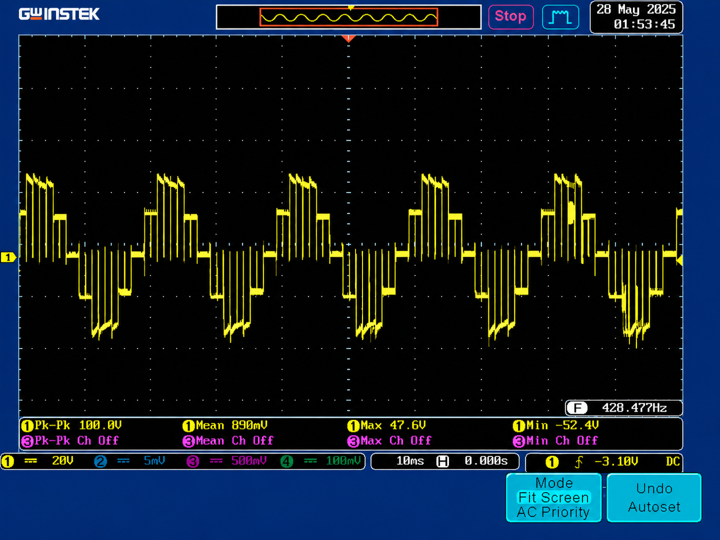
This is the result that satisfies the graduation spec: 5 distinct cascade output levels visible without an output filter, at 100 V cascade output, under sustained operation. Both bridges thermally balanced; no protection trips during the run.
Other scope traces
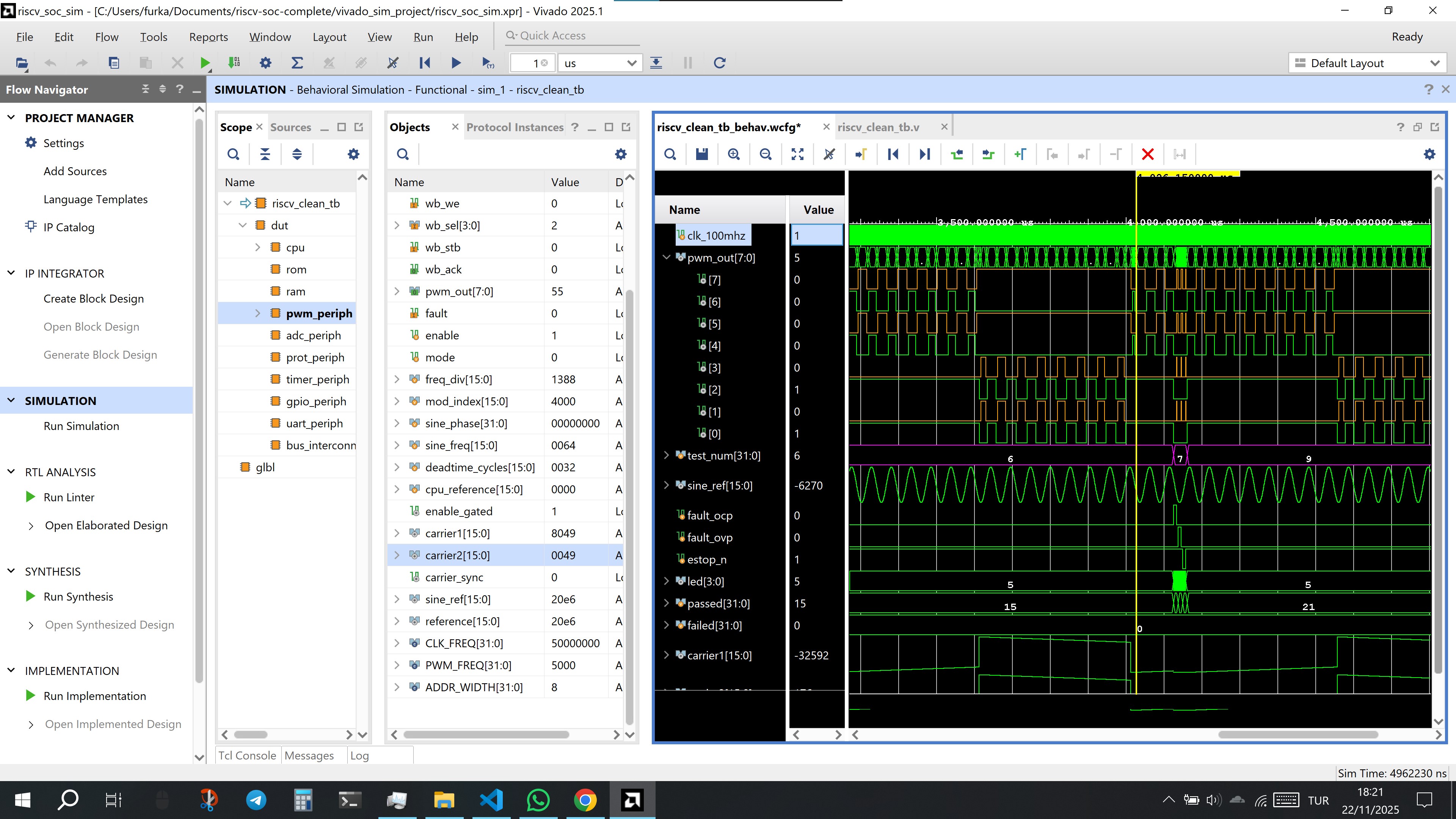
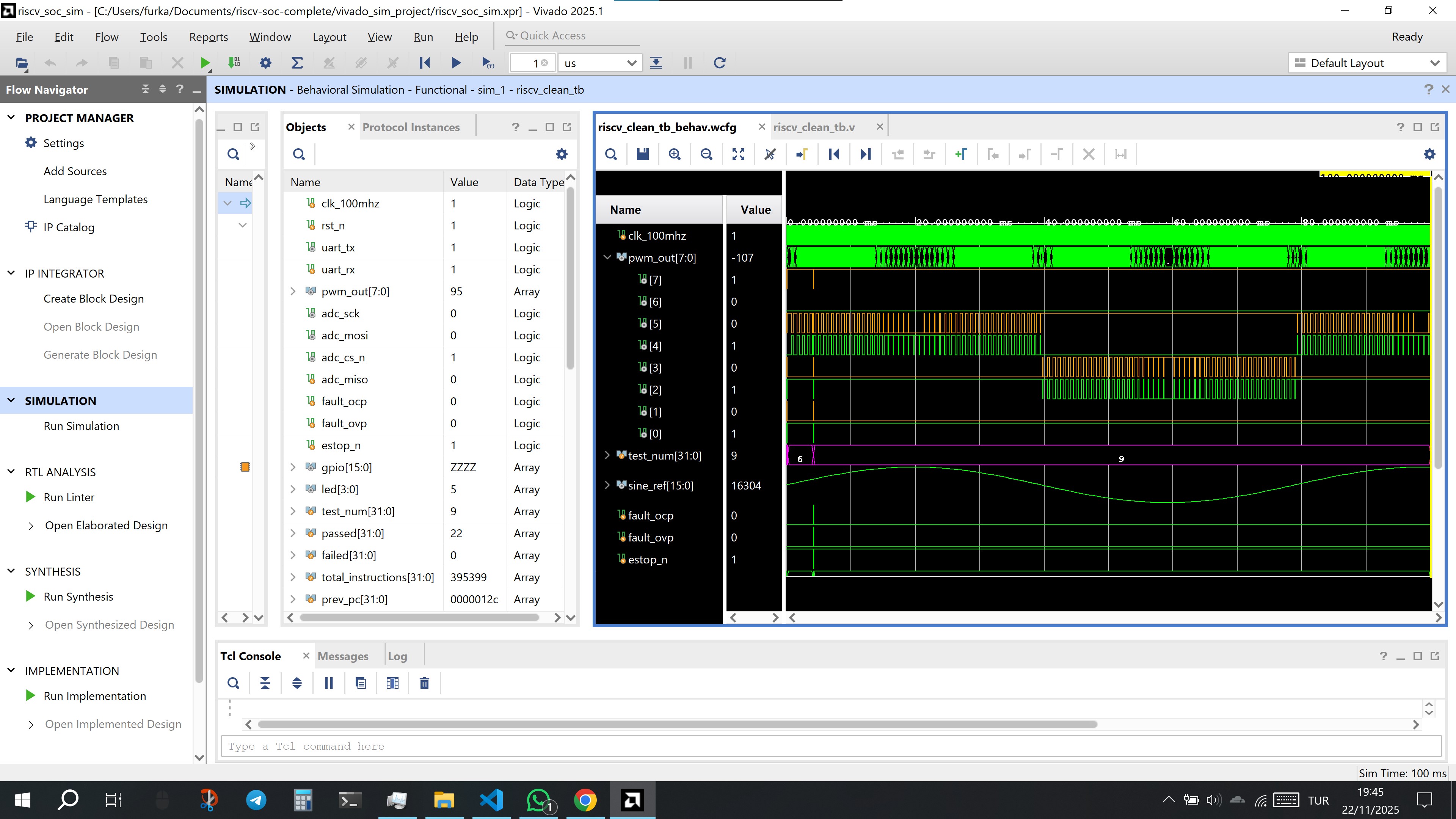
Other captures from the PSC bench run — earlier sweeps that show the path to the headline above:
Earlier bench session (2026-03-05)
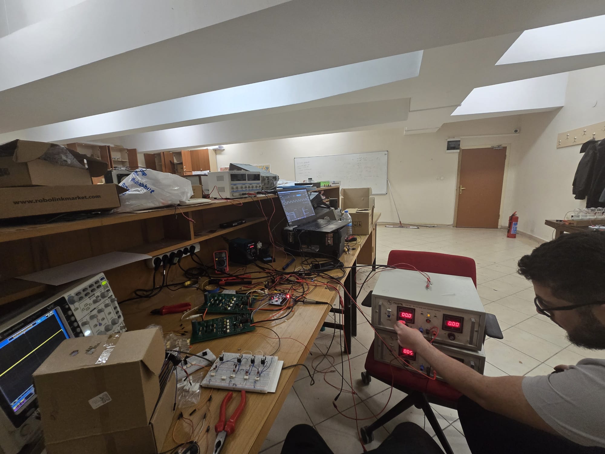
Photos from a mid-development bench day, before the final cleanup. Useful for context — they show the boards in their bring-up configuration.


Earlier breadboard prototype
For continuity, the earlier breadboard half-bridge with the gate-drive LED visibly switching during bring-up of the gate drive itself:

This is not the as-built PCB — it is the team's debug rig used while characterizing the gate drive before committing to the PCB layout.
What's still pending
- More dead-time scope captures (rising / falling edge zoom).
- Thermal scan of the bridges under sustained PSC load.
- Individual close-up shots of each populated PCB module (top + bottom).
(Tracked at _AGENT_TRACKER.md — artifact #8.)