Iteration history
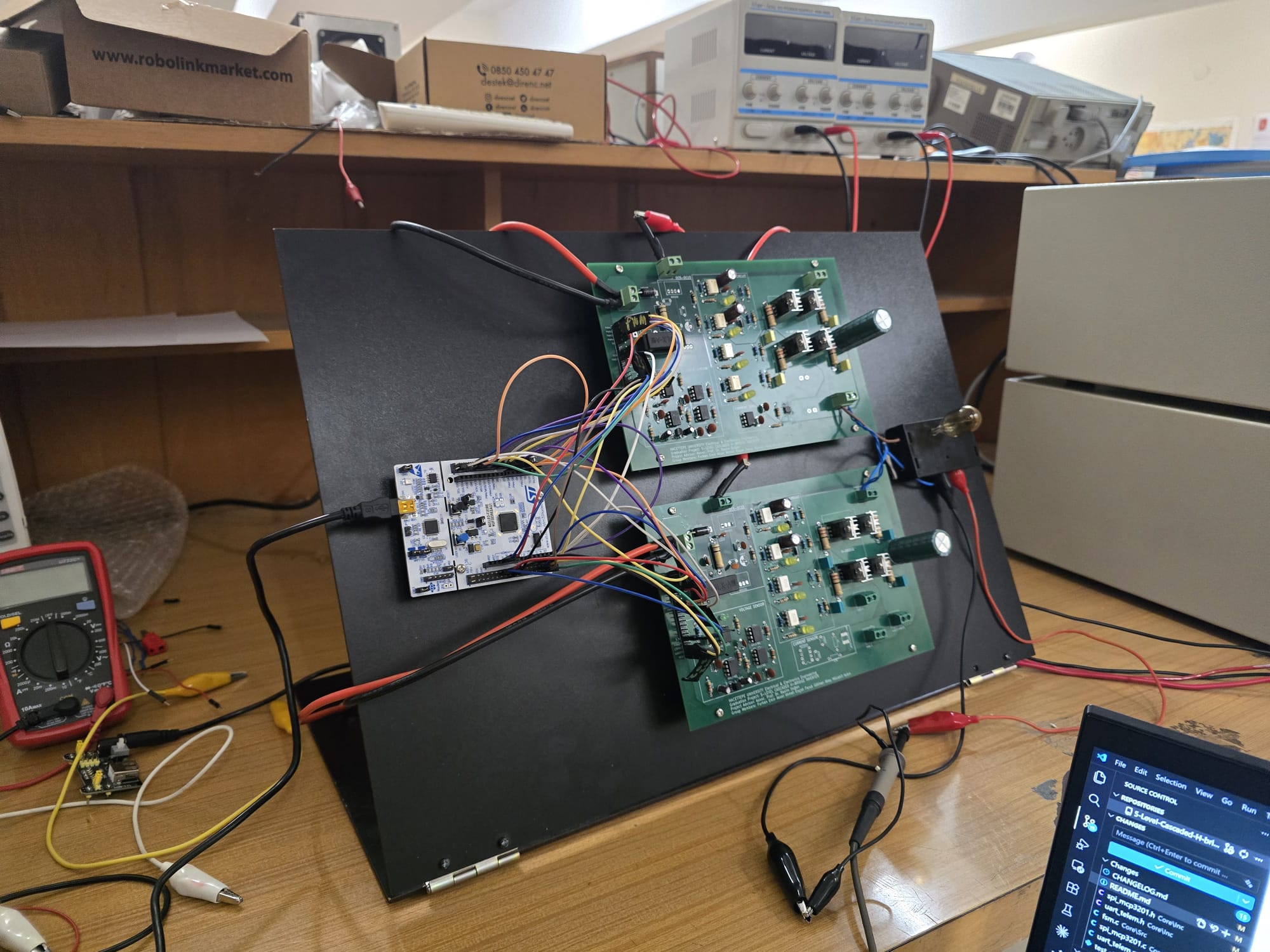
The story of the hardware as it evolved from the first board to the demonstrated design. Each page documents what was attempted, what failed, what was learned, and what changed for the next round — written honestly, with the failures in plain view rather than smoothed over.
| Iteration | Headline | Status |
|---|---|---|
| Iteration 1 | Single dual-bridge PCB, IRFZ44N MOSFETs, IPD LS-PWM | Superseded |
| Iteration 2 | Revised gate-drive routing; bootstrap-timing lessons | Superseded |
| Iteration 3 | Per-bridge isolation, MISO topology rework, MOSFET pin-mismatch errata | Superseded |
| Iteration 4 | Two identical single-bridge modules, IRFB4110, PSC-PWM | As-built, bench-validated, demonstrated |
Why iterating like this matters
The project's headline result — 5 distinct cascade levels visible on the scope at 100 V output, both bridges thermally matched — is not what iteration 1 produced. It took three rounds of bench-discovered failures and one re-architecture to reach.
Reading the four pages in order gives the engineering decisions in their original context: which assumptions were initially defensible, which broke under bench load, and which corrections compounded into the iteration-4 design. The design notes cover the why of specific decisions; this section covers the when and the what triggered the change.
Where the artifacts live
| Iteration | What survives |
|---|---|
| Iteration 1 | v3.1 BOM (under legacy/iteration-3/ for convenience). No KiCad files. |
| Iteration 2 | None preserved. |
| Iteration 3 | KiCad zip backups (working tree + a mid-iteration snapshot). |
| Iteration 4 | Full KiCad project + gerbers + populated photos at hardware/single-bridge-v4/. |